JBUS protocol
This system customizes a data structure: a variable, which is the source of data for a control and the bridge between controls. Each variable has a number of attributes, the ones related to communication: read/write type and register number. The read/write type is whether or not the control can be read or written externally when communicating with the outside world. The register number is the address number of the register in the MODBUS protocol or custom protocol. For the external communication object, the invisibility of the variable and the operation of the value of the variable are realized by operating the corresponding registers. Variables can be assigned a unique register address when they are created, a step that is realized by the user when editing the variable during IDE development.
1. Overall design of the JBUS protocol
The communication work of the whole system is mainly to realize the read/write operation of the variables, so as to transfer the data to the corresponding control. The communication protocol indexes the variables according to the register number, finds the variable with the same address, and then realizes the read/write operation according to the variable read/write type attribute and the communication requirement. The communication architecture is as follows:

The principle of the two communication protocols is very similar, the architecture is basically the same, the difference is that the custom protocol in the absence of master-slave mode, is an equal communication method, in addition to the MODBUS communication protocol on the host control slave control concept. The basic structure of the customized communication protocol can be divided into three layers, respectively, the physical layer and data link layer, protocol layer, user layer.
(1) Physical layer and data link layer: used to complete the configuration of the communication carrier, the use of serial communication, you need to configure the serial port baud rate, parity, interrupt, etc., but also need to configure the timer used for timing, including configuration of the timing of the timer time, timing interrupt. The data link layer implements data frame caching and frame grouping.
(2) Protocol layer: Used for data frame verification, function analysis, etc., and pass valid data to the user layer.
(3) User Layer: The user processes the data from the protocol layer.
This layered structure makes the communication protocol portable, can be based on different hardware environments to come to complete the underlying functional configuration, while the user layer code can be modified according to the design of functional requirements.
2. Design of data frame structure
2.1 Register transmission data structure
Functional Requirement: Since the variables use 32-bit values, the individual registers used for transmission by the custom protocol at the time of transmission are also 32-bit to keep the match.
The structure of the register communication data frame is shown in the table below:
![]()
The data frame uses 1 byte as the frame header checksum and 2 bytes CRC checksum ending to ensure the validity of the whole data frame.
The function code is 1 byte, when the function code is 0x01 it means transferring its own data to the outside, 0x02 means requesting data from the outside.
The start register address indicates that the address starts and fetches or transfers multiple registers backward.
The number of registers indicates the amount of communication data. If the function code is requesting data then the number of data bytes is 0, at this time there is no content in the data field, if it is transmitting data to the outside, then the data field is the starting address register data is sent first, each register is 4 bytes of data, the high byte is sent first, the low byte is sent later.
2.2 Virtual key transfer data frame structure
Functional Requirements: For products without touch screen, they need to be operated by keystrokes. Keystroke information can be transferred to the system through communication, and it is then necessary to create a separate format to recognize the virtual keystroke information.
The data frame structure is shown in the table below:
![]()
The key-value transfer function code is 0x03. The key-value data occupies two bytes in the data frame. The rest of the structure is the same as 2.1 Register Transfer Data Structure.
The key value table is as follows:

3. Check digit generation
This communication protocol uses 16-bit cyclic redundancy check (CRC), by or operation and shift operation on the communication data. Check digit generation operation is more complex, but this generates the check digit to ensure the validity of data communication, when the sender generates the check digit, the receiver side calculates with the received check digit does not match, then judge the current data frame is invalid.
Checksum generation is mainly for communication data, does not contain the start bit, stop bit and check bit in the serial communication packet. The steps are as follows:
(1) The initial checksum is 1 for all 16 bits, i.e. 0xFFFF.
(2) Different-or operation of 1 byte of the data frame with the checksum.
(3) Shift right by one bit, and complement the high bit with 0. If the data shifted right out of the low bit is 1, then the checksum code performs the different-or operation with 0xA001.
(4) Repeat the operation in step (3) until it is shifted to the right 8 times, then the byte processing is finished.
(5) Repeat step (2) until the entire packet is fully arithmetic, producing a 16-bit checksum.
After the sender puts the data to be sent into the data frame, he calculates the parity according to the data in the data frame and adds the parity bit to the end of the data frame.
4. Data frame caching
The end of frame uses timeout judgment to determine whether the current data frame is over. The entire data frame must be sent in a continuous stream. There are two time parameters that are very important in the data frame caching process, which are the reception interval between frame data bytes and the interval between data frames. The reception interval between frame data bytes cannot exceed 1.5 character transmission time; the interval between data frames is not less than 3.5 character transmission time.
As shown in the figure, it indicates the data frame caching interval:

Note: For these two parameters, due to the use of timer interrupt form to realize, in high-speed communication will lead to MCU timing interrupt time is short and too frequent. So when the baud rate is higher than 19200bps, two fixed time values are used, and here the corresponding two parameter times at 19200bps are used. According to the calculation, the transmission time of 3.5 characters is about 2ms, and the transmission time of 1.5 characters is about 885us. when the baud rate is lower than 19200bps, please calculate according to the transmission time of 3.5 characters and 1.5 characters to set the two time parameters.
The data frame caching flowchart is shown below:

5. State machine design
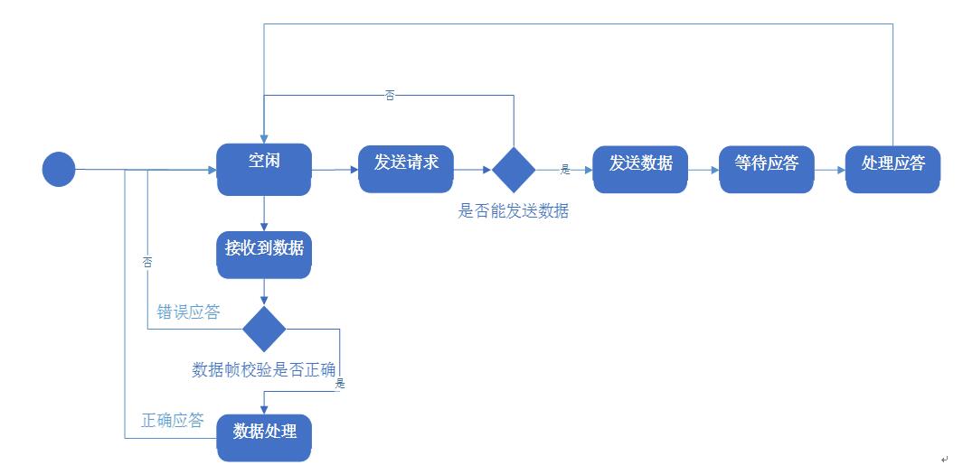
Here for the state machine is briefly explained. The idle state is the starting state, which means that the state can receive data or request to send data. When the data is received, it starts to enter the data frame cache, and at the end of the data frame cache, the data will be checked by the checksum code, if the checksum code detection fails, the current data is invalid, if the checksum code passes, it means that the data is normal, and it will be processed according to the user's set data and send the correct response.
6. User function interface
AHMI_READ(USHORT usRegAddr, USHORT usNReg)
Function Description: Requests an external communication object to send data
Parameter description: usRegAddr: register start address; usNReg: number of registers.
AHMI_WRITE(USHORT usRegAddr , USHORT usNReg , u32* pusDataBuffer)
Function Description: Transfer its own data to the external communication object
Parameter description: usRegAddr: register start address; usNReg: number of registers; pusDataBuffer: data buffer pointer
AHMIPoll()
Function description: state machine function, need to run regularly.
Parameter description: none
AHMIInit(UCHAR ucPort , ULONG ulBaudRate , eMBParity eParity)
Function Description: Initialize the communication serial port
Parameter description: usPort: serial port number; ulBaudRate: serial port baud rate; eParity: serial port checksum method