MODBUS protocol
Modbus is a communication protocol commonly used in industry. This protocol defines a message structure that a controller can recognize and use; it describes the process by which a controller requests access to other devices, how it responds to requests from other devices, and how it detects and logs errors. It establishes a common format for message field patterns and content.
1. Description of the Modbus protocol
The Modbus protocol defines a simple Protocol Data Unit (PDU) independent of the underlying communication layer. The mapping of the Modbus protocol on a specific bus or network enables the introduction of a number of additional fields on the Application Data Unit (ADU).
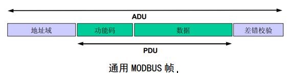
The client (host) that initiates the Modbus transaction creates the Modbus application data unit. The function code indicates to the server (slave) which operation will be performed.The Modbus protocol standardizes the format of the host's request, as shown above.
The maximum length of a Modbus ADU is 256 bytes.
1-byte address field indicating the slave address. A total of 256 addresses can be encoded from 0-255.Modbus masters do not have addresses, slaves must have unique addresses. Address 0 is for broadcast mode, i.e., the master publishes messages to all slaves. Addresses 1-247 are individual slave addresses and 248-255 are reserved addresses. For one-to-one communication, the slave address is usually defined as 1.
1-byte function code that encodes the function code field of the Modbus data unit. Valid function codes range from decimal 1-255 (128-255 is reserved for exception responses). When a message is sent from the host to the slave device, the function code informs the slave which operation to perform. Some function codes have sub-function codes to implement multiple operations.
Several bits contain a data field of request and response parameters that the slave uses to perform the operation defined by the function code. This field also includes discrete item and register addresses, the number of items processed, and the actual number of data bytes in the field. The data field can be non-existent (0 length) in certain requests, in which case the server does not need any additional information. The function code only describes the operation.
2-byte error check, the result of the calculation of the "redundancy check" performed on the contents of the message, the implementation of which is described later.
The Modbus serial link protocol is a master-slave protocol. At the same time, only one master is connected to the bus, and one or more slaves (maximum number 247) are connected to the same serial bus.Modbus communication is always initiated by the master. Slaves never send data without receiving a request from the master. Slaves never communicate with each other. The host will only initiate one Modbus transaction at a time.
The response data field from the slave to the host includes the requested data if there are no errors related to the requested Modbus function in a correctly received Modbus ADU. If there is an error related to the requested Modbus function, then the field includes an exception code that the slave application can use to determine the next action to perform.
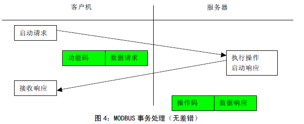
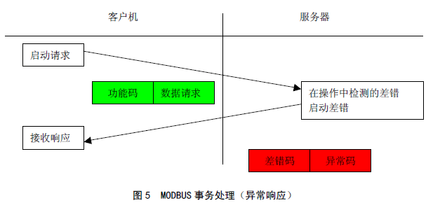
When the slave responds to the host, it uses the function code field to indicate either a normal (no error) response or the occurrence of some kind of error (called an exception response). For a normal response, the slave responds only to the original function code. The following diagram shows how a transaction handles normal and abnormal.
For an exception response, the slave returns a code equivalent to the original function code, setting the highest valid bit of that original function code to a logic 1.
The Modbus protocol defines three types of PDUs. they are:
Modbus request PDU, mb_req_pdu;
Modbus response PDU, mb_rsp_pdu;
Modbus exception response PDU, mb_excep_rsp_pdu.
2. Modbus data model
Modbus is based on 4 data models with different characteristics on the tables.
The following section focuses on writing coils and writing holding registers.

3. Function codes
3.1 Function code definitions
Write multiple coils: function code 0x0F
Write multiple registers: function code 0x10
3.2 Write multiple registers (0x10)
Table 2 Host Request PDUs

Table 3 Slave response

N is the number of registers.
If an error occurs, the slave returns a 1-byte error code 0x90 and a 1-byte exception code 01 or 02 or 03 or 04
For example, the host sends: 01 10 00 0B 00 01 02 00 01 66 EB
01 means writing data to the slave at address 1, 10 is the function code, 00 0B is the starting address, 00 01 means 1 register, 02 means the length of the data written is 2 bytes, 00 01 is the content of the data written, and 66 EB is the parity bit automatically generated by the host.
Therefore, this message indicates that "00 01" is written to the address starting from 00 0B of slave No.1.
3.3 Write multiple coils (0x0F)
Table 4 Host Request PDUs

The number of output bytes N = the number of output coils/8, and if the remainder is not equal to 0, it is rounded up by adding 1.
Table 5 Slave Response

Logic 1 corresponds to the switching output "ON" and logic 0 corresponds to the switching output "OFF".
If the number of coils written is not a multiple of 8, the unused bits in the last byte are filled with zeros.
If an error occurs, the slave returns the 1-byte error code 0x8F and the 1-byte exception code 01 or 02 or 03 or 04.
For example, the host sends: 01 0F 00 00 00 00 0A 02 A0 01 5C F8
01 means to write coils to the slave at address 1, 0F is the function code, 00 00 is the starting address, 00 0A means to write 10 coils, 02 means that the data written occupies 2 bytes, A0 01 is the content of the data written, and 5C F8 is the parity bit automatically generated by the host.
A0 01 is written in binary form as: 1010 0000 0000 0001, where 1010 0000 is the 7th bit - the 0th bit of the actual data, the last two bits 01 in 0000 0001 are the 9th and 8th bits of the actual data, and the first 6 bits are the complementary 0. Therefore, the actual transmission of the 10 coil volume from low to high is: 0000 0101 10.
Therefore, this message indicates that 10 coils, 0000 0101 10, are written to the address starting from 00 00 on slave No. 1.
4. RTU transmission mode
The device uses RTU mode.
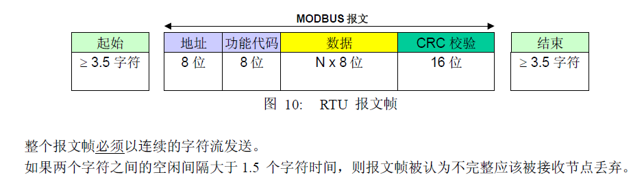
When a device communicates over a Modbus serial link using RTU (Remote Terminal Unit) mode, each 8-bit byte in the message contains two 4-bit hexadecimal characters. The main advantage of this mode is higher data density and higher throughput than ASCII mode at the same baud rate. Each message must be transmitted in a continuous stream of characters.
The format of each byte (11 bits) in RTU mode is.
Coding system: 8-bit binary
Each 8-bit byte in the message contains two 4-bit hexadecimal characters (0-9, A-F).
Bits per Byte: 1 Starting bit
8 data bits, lowest valid bit sent first
1 bit for parity
1 stop bit
To ensure maximum compatibility with other products, it is recommended that the parity check mode not be used. The default checksum mode must be even parity. 2 stop bits are required when using no parity.
When transmitting, each character or byte is sent in this order (left to right).
![]()
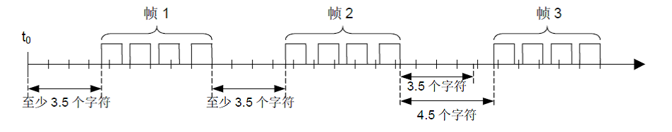
Modbus message RTU frames
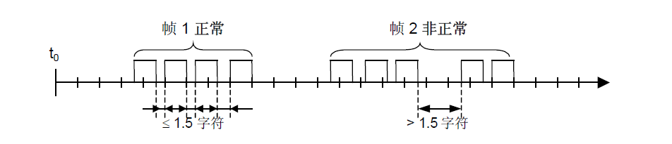
Modbus messages are constructed by the sending device as frames with known start and end markers. This allows the device to receive new frames at the beginning of the message and to know when the message ends. Incomplete messages must be detected and an error flag must be set as a result. In RTU mode, message frames are distinguished by an idle interval of at least 3.5 characters. In the following sections, this time interval is referred to as t3.5.
5. CRC checksums
The RTU mode contains an error checking field based on the Cyclical Redundancy Checking (CRC) algorithm, which is performed on the entire message content. This check is performed regardless of whether the message has parity or not.
The CRC contains a 16-bit value consisting of two 8-bit bytes.
The CRC field is appended as the last field of the message. After calculation, the low byte is appended first, followed by the high byte.The CRC high byte is the last subsection of the message sent.
The value of the CRC appended to the message is calculated by the sending device. The receiving device recalculates the value of the CRC when it receives the message and compares the result of the calculation with the actual CRC value received. If the two values are not equal, it is an error.
To calculate the CRC, a 16-bit register is preloaded with all 1's, and the subsequent calculation is performed on consecutive 8-bit bytes in the message. Only the 8 data bits in the character are involved in the CRC generation, the start, stop and parity bits are not involved in the CRC calculation.
During the CRC generation process, each 8-bit character is iso-orthogonal to the value in the register. The result is then shifted (Shift) 1 bit towards the least significant bit (LSB) and the highest significant bit (MSB) position is zeroed. The LSB is then extracted and examined: if the LSB is 1, the value in the register is isochronized with a fixed preset value; if the LSB is 0, no isochronization is performed.
This process is repeated until 8 shifts have been performed. After the last (8th) shift and related operations are completed, the next 8-bit byte is then isomorphic to the current value in the register, and then the process is repeated 8 times as described above. The final value in the register, obtained when all bytes in the message have been calculated, is the CRC.