Wave Filter
I. Background
If the received message is not Wave Filtered, the volatility is very strong, directly parsing the message value and assigning it to the corresponding Tag, it will directly lead to p oor display effect such as the problem of frequent pointer jumps. Wave Filter tool can better solve this problem.
The Wave Filter introduces a damping algorithm, which is a common motion model to realize the visual effect similar to mechanical instrumentation.IDE's Wave Filter supports first-order damping, second-order damping and linear damping algorithms.
2. Principle
2.1 Principle of Damping Algorithm
The output quantity will not change immediately with the input quantity, but will gradually reach the new value after a specific time. For example, the pointer will not rotate to the value of the input signal immediately when the input signal changes, but there is a process of gradually moving to the position, so that if the input signal jumps back and forth and fluctuates, then the pointer can remain stable.
2.2 First order damping algorithm
The input-output model of the algorithm is shown below:
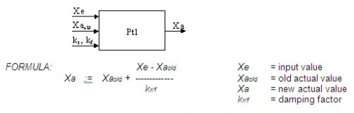
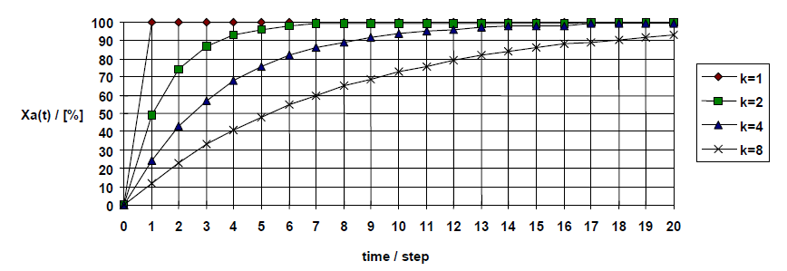
Based on the last actual value Xaold (the value displayed at the previous moment) and the input value Xe, and the parameter k, the value Xa that should be displayed at the current moment is calculated. The curve of the output result is as follows, the larger the value of k, the slower the approximation:
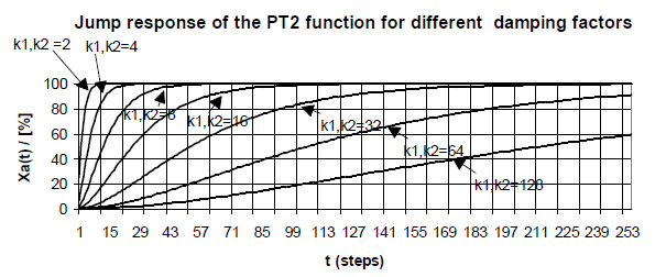
2.3 Second-order damping algorithm
Second-order damping is done 2 times the operation of the first-order damping algorithm and the two parameters k can be set separately. The algorithm input and output models are as follows:
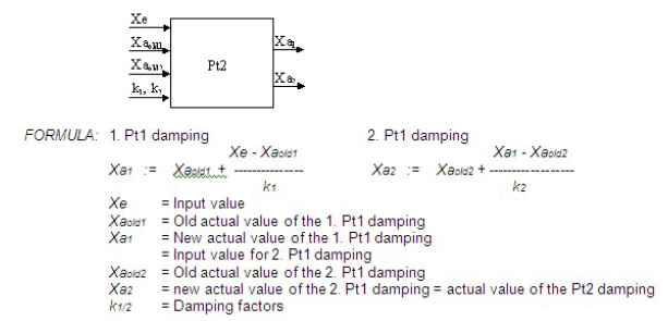
The curves of the output results are as follows, the asymptotic process of the second-order damping is smoother than the first-order damping:
2.4 Linear Damping Algorithm
The motion model of linear damping is simple, it is a linear process, the step size of each approximation and the period of one approximation can be adjusted to realize the adjustment of the approximation speed. Linear damping is practical and the ends of first and second order damping are replaced with linear damping.
III. Wave Filter Parameter Settings
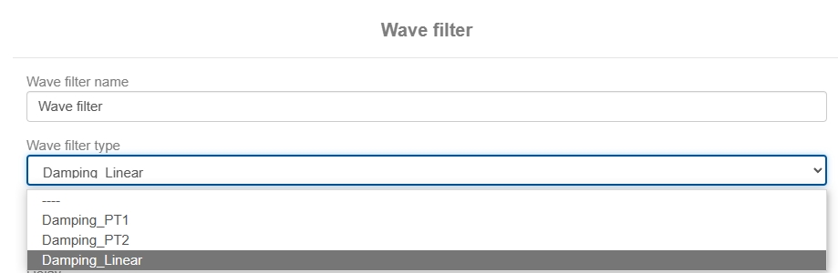
There are three damping algorithms available in the Wave Filter. Click Add Wave Filter under the Variables tab in the Property Bar to bring up the Wave Filter Settings window.
3.1 First order damping (PT1)
The back-end definitions for first-order damping are as follows, some of which are system parameters that do not need to be set by the user:

The parameters that need to be set by the user in the ide interface include the following
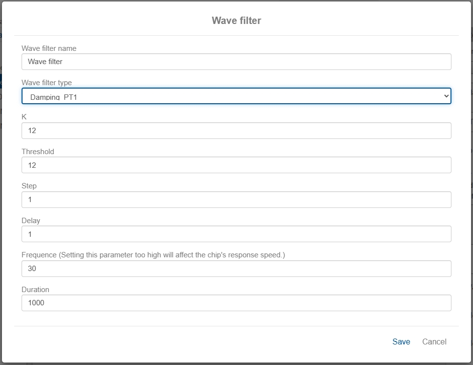
mK - K Damping parameter, an integer greater than 1. Used to adjust the speed of the damped motion.
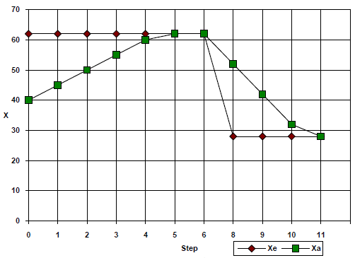
mThreshold - Threshold, because the slope of the back end of the first-order damping algorithm is too small, the approximation is very slow, so the back section is directly replaced by linear damping, when the difference between the current value and the target value is less than the threshold, the system automatically replaces the first-order damping with linear damping. If you find that the final approximation is not possible, for example, the target speed value is 80, but the final result can only go up to 75 after Wave Filtering, then you can try to adjust the threshold to greater than 5.
mStep - Step - Step of the latter part of the linear damping, on behalf of the linear slope, generally 1, but in order to meet the parameters such as speed 8000 such an order of magnitude, for example, from 6000-8000, you may need to self-increase each time to speed up the speed of 10, mStep needs to be set to 10.
mDelayMax - the upper limit of the Delay counter, also represents the linear slope of the latter section, in order to solve the need for mStep set to 1 is also too fast, for example, need to increase from 10 to 15, every 8 operations before adding 1, mStep is set to 1, mDelayMax is set to 8.
Frequence: the frequency of damping Wave Filter, i.e. how many times per second the value will be Wave Filtered continuously.
Duration: the duration of the damping Wave Filter, in ms.
3.2 Second order damping (PT2)
Definition of the back end of second order damping:
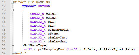
The parameters that need to be set by the user in the ide interface include the following:
mK1 - K1 Damping parameter, integer greater than 1. Used to adjust the speed of the damped motion.
mK2 - K2 Damping parameter, integer greater than 1. Used to adjust the speed of the damped motion.
mThreshold - Threshold Threshold, similar to first-order damping, is replaced with linear damping when the slope at the back end of the algorithm is too small, the approximation is very slow, and the difference between the current value and the target value is less than the threshold.
mStep - Step The step of linear damping in the back end of the Step, represents the slope of the linear, usually 1, but in order to satisfy parameters such as RPM 8000 which is an order of magnitude, e.g., from 6000-8000, it may be necessary to accelerate the speed up by 10 each time of self-incrementation, mStep will need to be set to 10.
mDelayMax - the upper limit of the Delay counter, also represents the linear slope of the latter section, in order to solve the need for mStep set to 1 is also too fast, for example, need to increase from 10 to 15, every 8 operations before adding 1, mStep is set to 1, mDelayMax is set to 8.
Frequence: the frequency of damping Wave Filter, i.e. how many times per second the value will be Wave Filtered continuously.
Duration: the duration of the damping Wave Filter, in ms.
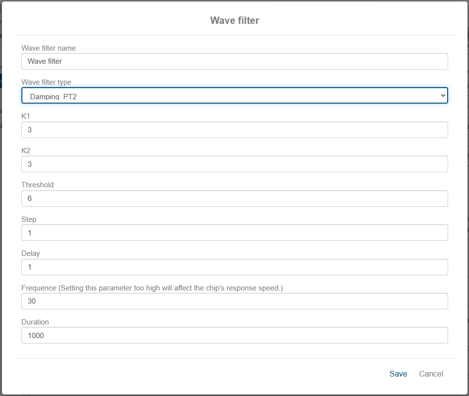
3.3 Linear Damping
Definition of the back end of linear damping:

The parameters that need to be set by the user in the ide interface include the following:
mStep - Step The step of the linear damping, represents the slope of the linear, usually 1, but in order to satisfy parameters such as RPM 8000 which is an order of magnitude, e.g. from 6000-8000, it may be necessary to accelerate the speed up by 10 each time of self-incrementation, and the mStep will need to be set to 10.
mDelayMax - the upper limit of the Delay counter, representing a linear slope, in order to address the need for mStep to be set to 1 which is also too fast, e.g., it needs to be incremented from 10 to 15, with 1 being added only every 8 operations, mStep is set to 1 and mDelayMax is set to 8.
Frequence: the frequency of damping Wave Filter, i.e. how many times per second the value will be Wave Filtered continuously.
Duration: the duration of the damping Wave Filter, in ms.
Example of Wave Filter application
Let's take the most commonly used linear damping as an example, and set the following parameters for the Wave Filter:
Select a variable, enable registers, and enable Wave Filters.
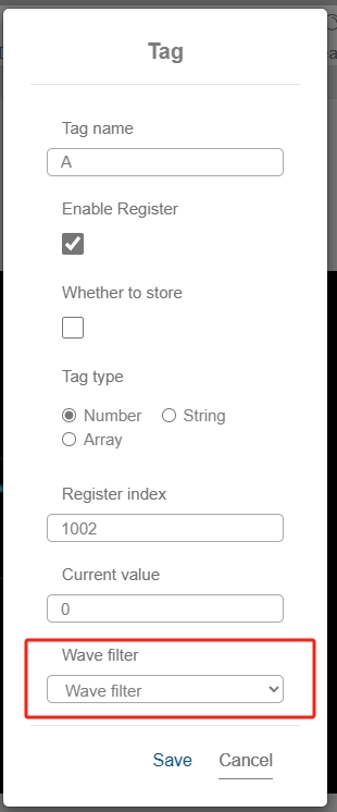
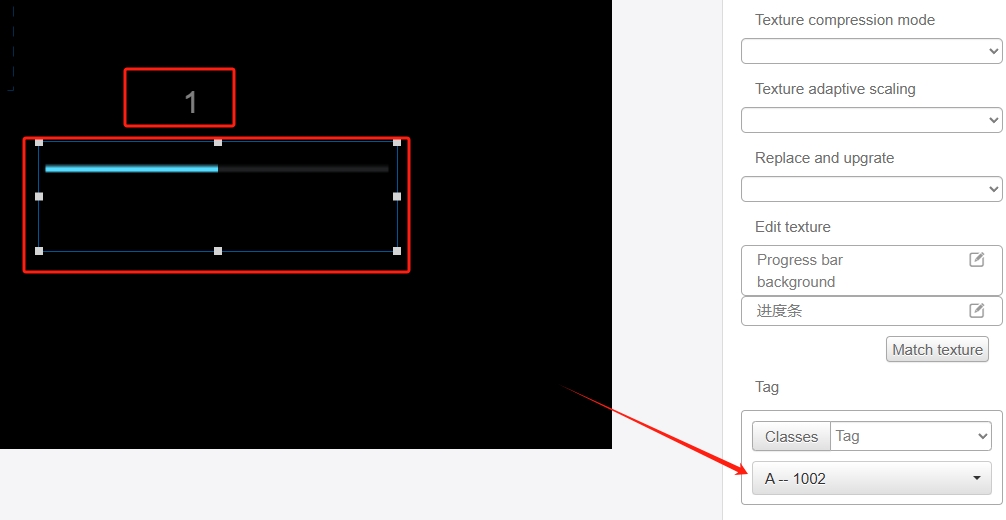
For visualization, bind the variables to the number and progress bar controls. In the debugging interface, modify the value of the variable, and you can see the number and progress bar gradually change from the initial value to the input value.